
bxm's IT Story
GNS3 코드 정리본 본문
첫번째 모형) VLAN과 Trunking을 활용한 왼쪽 SW1에 연결된 R1 모형

<순서>
1. SW1과 SW2에서 각 포트에 연결된 단자에 각각의 VLAN 값을 넣어준다.
2. SW1은 R1과 SW2 // 그리고 SW2는 SW1과 Trunking 시킨다.
3. R1에서 VLAN 10과 연결될 0/0.10 포트와, VLAN 20과 연결될 0/0.20 포트에 Encapsulation dot1q 를 해주고,
각 VLAN에 입력될 Gateway 주소를 입력해준다.
4. PC1 부터 PC4 까지 각 VLAN에 맞는 Gateway 주소와, 자신만의 IP 주소를 Mask 값과 함께 입력해준다.
##
## SW1위의 R1 / SW1, SW2 스위치 2개 / SW1-PC1,2 SW2-PC3,4
## show cdp nei // show ip int br // show int tr // show vlan-sw 오류 확인시 써먹기.
##
[공통]
ena
conf t
no ip domain lookup
line c 0
logg sy
exec-timeout 0
exit
line vty 0 4
pass cisco
exit
hostname
[SW1]
no ip routing
vlan 10
exit
vlan 20
exit
int f1/1
sw mo ac
sw ac vlan 10
exit
int f1/2
sw mo ac
sw ac vlan 20
exit
int range f1/9 , f1/15
sw tr enc dot
sw mo tr
end
wr
[SW2]
no ip routing
vlan 10
exit
vlan 20
exit
int f1/3
sw mo ac
sw ac vlan 10
exit
int f1/4
sw mo ac
sw ac vlan 20
exit
int f1/9
sw tr enc dot
sw mo tr
end
wr
[R1]
int f0/0
no shut
exit
int f0/0.10
enc dot 10
ip address 1.1.10.254 255.255.255.0
exit
int f0/0.20
enc dot 20
ip address 1.1.20.254 255.255.255.0
exit
[PC1]
no ip routing
ip default-gateway 1.1.10.254
int f0/0
no shut
ip address 1.1.10.1 255.255.255.0
[PC2]
no ip routing
ip default-gateway 1.1.20.254
int f0/0
no shut
ip address 1.1.20.2 255.255.255.0
[PC3]
no ip routing
ip default-gateway 1.1.10.254
int f0/0
no shut
ip address 1.1.10.3 255.255.255.0
[PC4]
no ip routing
ip default-gateway 1.1.20.254
int f0/0
no shut
ip address 1.1.20.4 255.255.255.0
<확인 절차>
PC1) ping 1.1.10.254 // ping 1.1.20.254 // ping 1.1.20.2
ping 1.1.10.3 // ping 1.1.20.4
두번째 모형) VLAN과 Trunking을 활용한 오른쪽 SW2에 연결된 R1 모형

<순서>
1. SW1과 SW2에서 각 포트에 연결된 단자에 각각의 VLAN 값을 넣어준다.
2. SW1은 SW2 // 그리고 SW2는 R1, SW1과 Trunking 시킨다.
3. R1에서 VLAN 10과 연결될 0/0.10 포트와, VLAN 20과 연결될 0/0.20 포트에 Encapsulation dot1q 를 해주고,
각 VLAN에 입력될 Gateway 주소를 입력해준다.
4. PC1 부터 PC4 까지 각 VLAN에 맞는 Gateway 주소와, 자신만의 IP 주소를 Mask 값과 함께 입력해준다.
##
## SW2위의 R1 / SW1, SW2 스위치 2개 / SW1-PC1,2 SW2-PC3,4
## show cdp nei // show ip int br // show int tr // show vlan-sw 오류 확인시 써먹기.
##
[공통]
ena
conf t
no ip domain lookup
line c 0
logg sy
exec-timeout 0
exit
line vty 0 4
pass cisco
exit
hostname
[SW1]
no ip routing
vlan 10
exit
vlan 20
exit
int f1/1
sw mo ac
sw ac vlan 10
exit
int f1/2
sw mo ac
sw ac vlan 20
exit
int f1/9
sw tr enc dot
sw mo tr
end
wr
[SW2]
no ip routing
vlan 10
exit
vlan 20
exit
int f1/3
sw mo ac
sw ac vlan 10
exit
int f1/4
sw mo ac
sw ac vlan 20
exit
int range f1/9 , f1/15
sw tr enc dot
sw mo tr
end
wr
[R1]
int f0/0
no shut
exit
int f0/0.10
enc dot 10
ip address 1.1.10.254 255.255.255.0
exit
int f0/0.20
enc dot 20
ip address 1.1.20.254 255.255.255.0
exit
[PC1]
no ip routing
ip default-gateway 1.1.10.254
int f0/0
no shut
ip address 1.1.10.1 255.255.255.0
[PC2]
no ip routing
ip default-gateway 1.1.20.254
int f0/0
no shut
ip address 1.1.20.2 255.255.255.0
[PC3]
no ip routing
ip default-gateway 1.1.10.254
int f0/0
no shut
ip address 1.1.10.3 255.255.255.0
[PC4]
no ip routing
ip default-gateway 1.1.20.254
int f0/0
no shut
ip address 1.1.20.4 255.255.255.0
<확인 절차>
PC1) ping 1.1.10.254 // ping 1.1.20.254 // ping 1.1.20.2
ping 1.1.10.3 // ping 1.1.20.4
세번째 모형) PPP-CHAP 방식에서 Native VLAN을 결합한 모형

<순서>
1. SW1과 SW2에서 각 포트에 연결된 단자에 각각의 VLAN 값을 넣어준다.
2. SW1은 R1과 Trunking 하되 VLAN 10은 Native로, SW2는 R2와 Trunking 하되 VLAN 30은 Native로
3.
4.
5.
##
## SW2위의 R1 / SW1, SW2 스위치 2개 / SW1-PC1,2 SW2-PC3,4
## show cdp nei // show ip int br // show int tr // show vlan-sw 오류 확인시 써먹기.
##
[공통 - R1,R2,SW1,SW2,PC1,PC2,PC3,PC4]
ena
conf t
no ip domain lookup
line c 0
logg sy
exec-timeout 0
exit
line vty 0 4
pass cisco
exit
hostname ##
[SW1]
conf t
no ip routing
vlan 10
exit
vlan 20
exit
int f1/1
switchport mode access
switchport access vlan 10
exit
int f1/2
switchport mode access
switchport access vlan 20
exit
int f1/15
switchport trunk encapsulation dot1q
switchport mode trunk
switchport trunk native vlan 10
[SW2]
conf t
no ip routing
vlan 30
exit
vlan 40
exit
int f1/3
switchport mode access
switchport access vlan 30
exit
int f1/4
switchport mode access
switchport access vlan 40
exit
int f1/15
switchport trunk encapsulation dot1q
switchport mode trunk
switchport trunk native vlan 30
do wr
[R1]
conf t
int f0/0
no shutdown
exit
int f0/0.10
encapsulation dot1q 10 Native
ip address 192.168.10.254 255.255.255.0
exit
int f0/0.20
encapsulation dot1q 20
ip address 192.168.20.254 255.255.255.0
exit
!
username R2 password cisco
!
int s1/0
no shutdown
encapsulation ppp
ppp authentication chap
ip address 1.1.12.1 255.255.255.252 (#30비트 이므로!!, 1.1.12.0/30)
exit
!
ip route 192.168.30.0 255.255.255.0 s1/0 1.1.12.2
ip route 192.168.40.0 255.255.255.0 s1/0 1.1.12.2
!
do wr
[R2]
conf t
int f0/0
no shutdown
exit
int f0/0.30
encapsulation dot1q 30 Native
ip address 192.168.30.254 255.255.255.252 (#30비트 이므로!!, 1.1.12.0/30)
exit
int f0/0.40
encapsulation dot1q 40
ip address 192.168.40.254 255.255.255.0
exit
!
username R1 password cisco
!
int s1/0
no shutdown
encapsulation ppp
ppp authentication chap
ip address 1.1.12.2 255.255.255.0
exit
!
ip route 192.168.10.0 255.255.255.0 s1/0 1.1.12.1
ip route 192.168.20.0 255.255.255.0 s1/0 1.1.12.1
!
do wr
[PC1]
conf t
no ip routing
ip default-gateway 192.168.10.254
int f0/0
no shutdown
ip address 192.168.10.1 255.255.255.0
do wr
[PC2]
conf t
no ip routing
ip default-gateway 192.168.20.254
int f0/0
no shutdown
ip address 192.168.20.2 255.255.255.0
do wr
[PC3]
conf t
no ip routing
ip default-gateway 192.168.30.254
int f0/0
no shutdown
ip address 192.168.30.3 255.255.255.0
do wr
[PC4]
conf t
no ip routing
ip default-gateway 192.168.40.254
int f0/0
no shutdown
ip address 192.168.40.4 255.255.255.0
do wr
네번째 모형) 프레임 릴레이


중간 명령어 :
- show ip route : 연결된 ip 확인
- show frame map : mapping 되어 있는 것 확인.
no frame map ip : 연결된 mapping 취소
R1~R4 까지 전부 실행.
그리고 그 전에 GNS3를 통해 실습했을 때의 기본 명령어
ena
conf t
no ip domain lookup
line c 0
logg sy
exec-timeout 0
exit
line vty 0 4
pass cisco
exit
hostname ## 그대로 적용.
int s1/0
no shut
encapsulation frame-relay
no frame-relay inverse-arp
#아무것도 안하고 내버려 놔두면, LMI 프로토콜이 돌아서 LMI가 DLCI에 있는 모든 회선을 엮어버림 (Full-mash로!!)
#그래서 DLCI가 모두 Mapping 되버리므로 우리는 3개만 쓰면 되므로 회선이 전부 Open이 되어버림.!!
clock rate 64000
#클럭을 왜주냐면 R4가 DCE 이므로, DCE에서 클럭을 주므로 각 라우터에서 클럭을 줘야함.
<물리적>
十자형
<논리적>
1자 형
[R1]
int lo0
ip add 1.1.1.1 255.255.255.0
int s1/0
ip address 1.1.12.1 255.255.255.0
frame-relay map ip 1.1.12.2 102 br
# PVC 상에서 R1->R2로 가는데 DLCI 102번을 타고 가므로 이걸 타고 가라고 알려주는 것임.
# broadcast와 multicast 2가지가 드나들게 허락해라. 라는 명령어임.

[R2]
###여기서 문제!!###
물리적으로는 단자가 1개인데, 논리적으로는 단자가 양 옆으로 2개임!! 이렇게 물리적 주소를 논리적 주소로 쪼갤때
쓰는 방법이 있다.
<프레임 릴레이 논리 인터페이스 규칙>
1. 주인터페이스와 멀티포인트는 동격이다.
2. 상대방 인터페이스가 하나 이상이면 p - to - p multipoint 모두 가능하다.
3. 상대방 인터페이스가 2개 이상이면 multipoint를 사용한다.
주인터페이스는 살려놓고, 서브인터페이스를 만들자(?)
int lo0
ip add 1.1.2.2 255.255.255.0
## 여기서부터 프레임 릴레이 논리 인터페이스 규칙임. m=multipointexit
int s1/0.12 m
ip add 1.1.12.2 255.255.255.0
frame map ip 1.1.12.1 201 br
exit
int s1/0.23 m
ip address 1.1.23.2 255.255.255.0
frame map ip 1.1.23.3 203 br

[R3]
int lo0
ip add 1.1.3.3 255.255.255.0
int s1/0.23 m
ip add 1.1.23.3 255.255.255.0
frame-relay map ip 1.1.23.2 302 br
exit
## R3<->R4는 point to point 이기 때문에 상대가 딱 1명이라서 ip를 지정할 필요가 없음. 그래서 명령어가 다름!!
int s1/0.34 p
ip add 1.1.34.3 255.255.255.0
frame interface-dlci 304
[R4]
int lo0
ip add 1.1.4.4 255.255.255.0
int s1/0.34 p
ip add 1.1.34.4 255.255.255.0
frame interface-dlci 403
<통신확인>
R1 -> R2

R2 -> R3

R3 -> R4

R1의 라우터는 'Show ip route'를 했을때 R2밖에 알지 못함. 한마디로 바로 옆 놈 이후로는 아예 모른단 것임.
R2와 R3 모두 마찬가지임. 그래서 라우팅을 통해 알려줘야함
목적지 네트워크 - 마스크 - 출구 인터페이스 - 넥스트

[R1] -> 이리 가려면 오른쪽으로 던지면 된다는 것을 알려주는 것임!!
conf t
ip route 1.1.2.0 255.255.255.0 s1/0 1.1.12.2
ip route 1.1.3.0 255.255.255.0 s1/0 1.1.12.2
ip route 1.1.4.0 255.255.255.0 s1/0 1.1.12.2
ip route 1.1.23.0 255.255.255.0 s1/0 1.1.12.2
ip route 1.1.34.0 255.255.255.0 s1/0 1.1.12.2

[R2] -> 자기와 붙은 위, 왼쪽, 오른쪽을 알고 있음. 하지만 그 이상은 알지 못함.

conf t
ip route 1.1.1.0 255.255.255.0 s1/0.12 1.1.12.1
ip route 1.1.3.0 255.255.255.0 s1/0.12 1.1.23.3
ip route 1.1.4.0 255.255.255.0 s1/0.12 1.1.23.3
ip route 1.1.34.0 255.255.255.0 s1/0.23 1.1.23.3

[R3] -> R1의 1.1, 12.0 // R2의 2.2 {여기까지는 왼쪽으로 던지고}
// R4의 4.4 {얘는 오른쪽으로 던지면 된다}를 모르는 상태임.
conf t
ip route 1.1.1.0 255.255.255.0 s1/0.23 1.1.23.2
ip route 1.1.12.0 255.255.255.0 s1/0.23 1.1.23.2
ip route 1.1.2.0 255.255.255.0 s1/0.23 1.1.23.2
ip route 1.1.4.0 255.255.255.0 s1/0.34 1.1.34.4

[R4] -> 4와 4.4 빼고 전부 모름
conf t
ip route 1.1.1.0 255.255.255.0 s1/0.34 1.1.34.3
ip route 1.1.2.0 255.255.255.0 s1/0.34 1.1.34.3
ip route 1.1.3.0 255.255.255.0 s1/0.34 1.1.34.3
ip route 1.1.12.0 255.255.255.0 s1/0.34 1.1.34.3
ip route 1.1.23.0 255.255.255.0 s1/0.34 1.1.34.3


<등록된 IP들을 축약 해보기> - 집 가서 축약 공부 제대로 마무리 하기.
R1]
no ip route 1.1.2.0 255.255.255.0 s1/0 1.1.12.2
no ip route 1.1.3.0 255.255.255.0 s1/0 1.1.12.2
no ip route 1.1.4.0 255.255.255.0 s1/0 1.1.12.2
no ip route 1.1.23.0 255.255.255.0 s1/0 1.1.12.2
no ip route 1.1.34.0 255.255.255.0 s1/0 1.1.12.2
ip route 1.1.0.0 255.255.192.0 s1/0 1.1.12.2
R2]
no ip route 1.1.1.0 255.255.255.0 s1/0.12 1.1.12.1
no ip route 1.1.3.0 255.255.255.0 s1/0.23 1.1.23.3
no ip route 1.1.4.0 255.255.255.0 s1/0.23 1.1.23.3
no ip route 1.1.34.0 255.255.255.0 s1/0.23 1.1.23.3
ip route 1.1.1.0 255.255.255.0 s1/0.12 1.1.12.1
ip route 1.1.0.0 255.255.192.0 s1/0.23 1.1.23.3
R3]
no ip route 1.1.1.0 255.255.255.0 s1/0.23 1.1.23.2
no ip route 1.1.12.0 255.255.255.0 s1/0.23 1.1.23.2
no ip route 1.1.2.0 255.255.255.0 s1/0.23 1.1.23.2
no ip route 1.1.4.0 255.255.255.0 s1/0.34 1.1.34.4
ip route 1.1.4.0 255.255.255.0 s1/0.34 1.1.34.4
ip route 1.1.0.0 255.255.255.0 s1/0.34 1.1.23.2
R4]
no ip route 1.1.1.0 255.255.255.0 S1/0.34 1.1.34.3
no ip route 1.1.2.0 255.255.255.0 s1/0.34 1.1.34.3
no ip route 1.1.3.0 255.255.255.0 s1/0.34 1.1.34.3
no ip route 1.1.12.0 255.255.255.0 s1/0.34 1.1.34.3
no ip route 1.1.23.0 255.255.255.0 s1/0.34 1.1.34.3
ip route 1.1.0.0 255.255.192.0 s1/0.34 1.1.34.3
[R1]
1. 연결된 IP들을 확인해보기.
show run | begin route (현재 연결된 IP들을 볼 수 있는 명령어이다.)

2. 연결된 IP들을 no ip 를 통해서 지워보기.
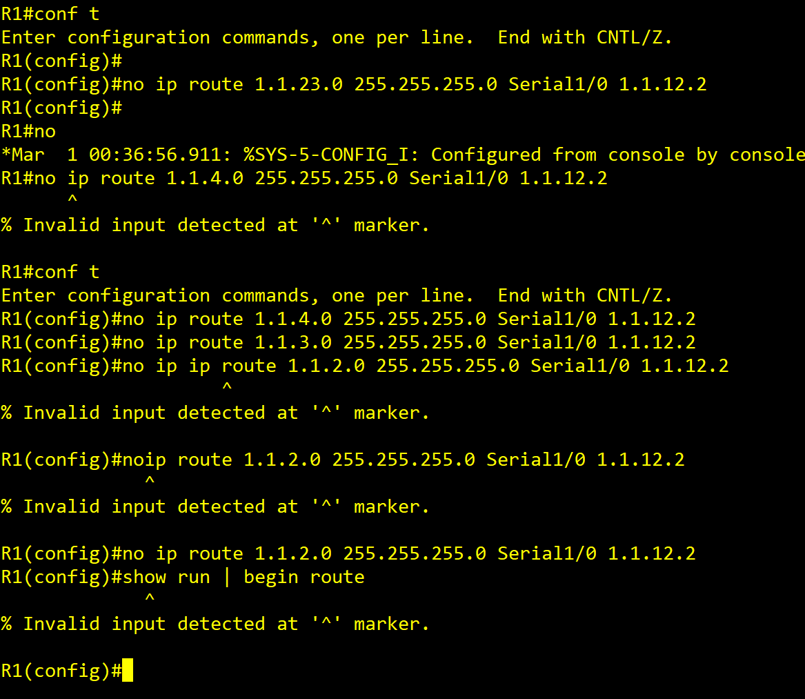
3. 다 지워진 것을 확인.

4. 축약하기
ip route 1.1.0.0 255.255.192.0 S1/0 1.1.12.2
## 1. 제일 큰 숫자가 Router3 -> Router4로 가는 34.0 이므로 2^5 <= 34 <= 2^6 이므로 /24에서 /18로 바꿈.
## 2. 1.1.0.0/18 -> 1.1.(0~63)/24랑 같은 말임.

[Longgest match rule] 엄청 중요!!
1.1.1.0 255.255.255.0 s1/0.12 1.1.12.1
1.1.0(0~63).0/24 255.255.192.0/18 s1/0.23 1.1.23.3
그러면 말에 모순이 있다. 1.0으로 갈땐 왼쪽으로 가라고 했는데
아래 까보니 0~63까지 포함이라서 1.0으로 갈때 오른쪽으로 가라고 또 말한다.
하지만 Longgest match rule 때문에 255가 192보다 비트로 보면 1의 수가 더 많기에 저것을 우선으로 라우팅하고
나머지 라우팅 안된 애들만 아래의 2번째 줄에 포함된다는 법칙이다.
https://csdaniel.tistory.com/72
롱기스트 매치 룰이란? (longest match rule)
: 라우터가 IP 패킷을 포워딩(라우팅)할 때 포워딩 테이블에서 해당 항목을 찾는 규칙 : IP 패킷의 목적지 IP 주소가 라우팅 테이블에 있는 수많은 목적지 IP 주소 중 일치하는 부분이
csdaniel.tistory.com
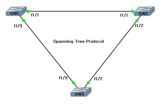
다섯번째 모형) Spanning-tree Protocol(1, No SVI)
'Network > Cisco (KEDU)' 카테고리의 다른 글
| Gateway 이중화(2) (0) | 2021.06.14 |
|---|---|
| Gateway 이중화(1) - HSRP (0) | 2021.06.14 |
| Spanning-tree 2차전 // 끝판왕(레벨3 스위치 3개 + 일반 스위치 1개) (0) | 2021.06.11 |
| Switch L3 interface (0) | 2021.06.11 |
| 스패닝 트리 프로토콜(STP,Spanning Tree Protocol) (1) | 2021.06.11 |


